Heavy loads do not forgive guesswork. A steel coil, industrial vessel, or concrete beam can shift suddenly when lifted, transported, or placed. Its center of gravity determines how weight is distributed around the load. If that point moves outside the support area, the load may tilt, slide, or overturn. Even experienced operators can misjudge an uneven object, especially when its shape hides internal weight.
Understanding How to determine the center of gravity for heavy loads is therefore essential for safer planning. Engineers typically review drawings, dimensions, material densities, and manufacturer data before selecting lifting points. They may also use balancing tests, load cells, or certified lifting equipment to confirm calculations. A practical check involves watching how a suspended load settles: the heavier side drops, while the center of gravity moves below the lifting point. Never treat this observation as a complete engineering assessment.
Small details matter. A partially filled tank changes its balance. Wet materials may shift during movement. Packaging, attachments, and damaged components can alter the original calculation. Reliable teams record each assumption, verify the load’s actual condition, and involve a qualified lifting professional when uncertainty remains. That discipline reflects real field experience, but it is not perfect. Measurements can be incomplete, and diagrams can become outdated. Careful reassessment keeps a theoretical center of gravity connected to the physical load in front of you.
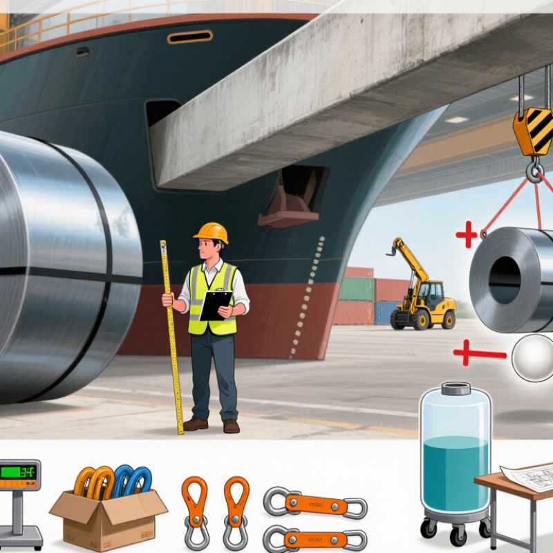
Center of gravity defines how a load’s mass is distributed around its support points. It is not always located at the geometric center. A steel frame with a thick motor on one side can have a noticeably offset center of gravity.
Engineers calculate it using each component’s mass and position.
For example, an 800-kilogram load may contain 600 kilograms at 0.4 meters and 200 kilograms at 1.2 meters. Its horizontal center of gravity is 0.6 meters from the reference point.
Small changes matter. Moving the motor 0.3 meters outward shifts the balance and increases the tipping moment.
The load remains stable only when its combined center of gravity stays within the support area. Uneven flooring, sudden braking, sling angles, and load sway can move that point beyond the base. Then, stability can disappear quickly.
HSE reported 138 workplace deaths and approximately 561,000 self-reported non-fatal injuries in Great Britain during 2023/24, showing why basic load control deserves careful attention. The International Labour Organization estimates 2.78 million work-related deaths annually worldwide, including fatal injuries and work-related diseases, reinforcing the need for disciplined planning.
A neat diagram can still mislead. Real loads rarely behave perfectly. Inspectors should verify actual weights, attachment points, floor conditions, and lifting height before movement. Center-of-gravity markings should be treated as evidence, not assumption. Crew communication also matters, because one unreported shift in mass can change the entire lifting plan.
Before lifting, locate the load’s center of gravity (CoG). It is the point where weight appears concentrated. A steel frame may look balanced, yet its motor, plate thickness, or trapped liquid can shift the CoG. Mark the point on the lift plan. Then position sling legs around it, not simply around the load’s visible center.
ASME B30.9-2023 addresses sling selection, inspection, and safe operating practices. Its guidance supports a basic field rule: keep the load stable and protect slings from damaging conditions. A small CoG error can increase tension in one sling leg. It can also make the load tilt, rotate, or swing during initial tensioning. Lift only a few centimeters first. Stop and check the angle, deformation, and hook alignment.
The U.S. Bureau of Labor Statistics recorded 5,283 fatal work injuries in 2023. Transportation and material-moving occupations accounted for 1,053 of those deaths. These figures cover more than rigging, but they show why controlled lifting matters. In practice, teams should verify the load weight, attachment points, sling angle, and nearby obstructions. Guessing is not a method. Still, drawings can be wrong, and field conditions change. Recheck the CoG when contents move, rigging shifts, or the load leaves its supports. A calm pause often prevents a violent correction.
Sling tension changes sharply when the angle becomes shallow. Measure the angle from the horizontal, not the floor. For two equal sling legs, use T = W ÷ (2 × sin θ).
The danger is easy to miss. A 30-degree sling may look stable while its hardware experiences severe loading. Center of gravity also matters. If the load shifts 100 millimeters, one leg can tighten suddenly while the other unloads. Unequal sharing can make the simple formula optimistic.
ASME B30.9 addresses sling selection, inspection, and safe use, while OSHA 1910.184 requires rated slings and proper protection. The U.S. Bureau of Labor Statistics reported 1,032 fatal injuries in transportation and material-moving occupations during 2023. Not every case involved rigging, but the figure shows why lifting controls deserve attention.
Before lifting, mark the estimated center of gravity and keep the hook directly above it. Check the sling angle, working load limit, connection points, and edge protection. Leave room for acceleration. A smooth lift matters.
My practical concern is this: calculations often assume equal legs and a static load, but real loads rarely cooperate perfectly. Recheck the plan when the load tilts, binds, or moves unexpectedly.
A heavy load can look stable while standing close to failure. The key question is simple: does the center of gravity (CoG) project inside the support polygon? This polygon is formed by the contact points of wheels, outriggers, or feet. If the vertical CoG line stays inside it, the load usually resists tipping. If it reaches an edge, even a small push, slope, or sudden stop can create rotation.
Consider a crate on four lifting feet. Its CoG may sit near the rear-right corner after uneven packing. That corner becomes the danger zone.
OSHA safety guidance states that forklift overturns cause about 25% of forklift-related workplace fatalities. The Health and Safety Executive also reports that workplace transport incidents contribute roughly a quarter of workplace deaths in Britain. These figures show why visual judgment alone is unreliable.
In practice, I mark the support points on the floor, then project the estimated CoG vertically. I also check acceleration, wind, suspended loads, and floor gradients.
A load can pass a static check and still tip during movement. My first estimate is often too optimistic. That is the uncomfortable part.
Load documentation may omit shifted contents, damaged pallets, or liquid movement. A wider polygon helps, but it does not remove uncertainty. Keep the CoG low, center the mass, and reassess after every change in load position or equipment setup.
Why Is Center of Gravity Important for Heavy Loads?
A heavy load can shift when its center of gravity sits outside the sling pattern. That movement can shock-load the sling and destabilize the lift. OSHA 29 CFR 1910.184 requires synthetic web slings to use a minimum 5:1 design factor. This means the sling’s breaking strength must be at least five times its rated working load. It does not permit lifting five times the rated capacity.
Check the sling tag, material, hitch type, and load angle before connecting. The rated capacity changes with vertical, basket, and choker hitches. It also changes when sling legs form an angle. For a two-leg sling at 30 degrees from horizontal, each leg carries about twice the load. That detail is easy to miss.
ASME B30.9 guidance also emphasizes inspection, protection from sharp edges, and removal of damaged slings. OSHA inspection guidance identifies cuts, burns, broken stitching, and chemical damage as serious warning signs. A clean-looking sling may still have hidden fiber damage. Do not guess.
Keep the hook above the load’s center of gravity. Lift slowly until the sling becomes lightly tensioned. Stop and watch for tilt, sliding, or uneven leg loading. The first test lift should be only a few inches. A rushed lift can expose a poor assumption. Recheck the capacity using the actual angle, hitch, and load weight, not an ideal diagram.
Illustrative two-leg sling calculations showing how an offset center of gravity changes leg loading and the minimum breaking strength required for a 5:1 design-factor check.
| Load Case | Load Weight | Center of Gravity | Pickup-Point Spacing | Sling Angle from Horizontal |
Left-Leg Vertical Share | Right-Leg Vertical Share | Left-Leg Tension | Right-Leg Tension | Minimum Breaking Strength per Leg (5 × Tension) |
Capacity Check |
|---|---|---|---|---|---|---|---|---|---|---|
| Case 1: Centered load | 4,000 lb | Centered between pickup points | 8 ft total (4 ft each side) |
60° | 2,000 lb | 2,000 lb | 2,309 lb | 2,309 lb | 11,545 lb per leg | Pass if MBS ≥ 11,545 lb |
| Case 2: 1 ft offset | 6,000 lb | 1 ft left of the midpoint | 8 ft total (4 ft each side) |
60° | 3,750 lb | 2,250 lb | 4,330 lb | 2,598 lb | 21,650 lb left leg 12,990 lb right leg |
Pass only if each leg meets its requirement |
| Case 3: 2 ft offset | 10,000 lb | 2 ft left of the midpoint | 10 ft total (5 ft each side) |
60° | 7,000 lb | 3,000 lb | 8,083 lb | 3,464 lb | 40,415 lb left leg 17,320 lb right leg |
High-risk imbalance; verify the heavier leg first |
For two equal legs, use T = W ÷ (2 × sin θ). Measure θ from the horizontal. At 30 degrees, each leg carries about half the total load. A 10,000-pound load creates roughly 10,000 pounds per leg. That is double the vertical arrangement. Shallow angles are deceptive.
With a 10,000-pound load, each leg carries 5,000 pounds at 90 degrees. At 60 degrees, each leg carries about 5,774 pounds. At 30 degrees, each leg carries 10,000 pounds. Small angle changes matter greatly.
The hook should sit directly above the load’s estimated center of gravity. If the load shifts 100 millimeters, one leg may tighten suddenly. The opposite leg may unload. Unequal sharing makes simple calculations optimistic. Loads rarely behave perfectly.
Project the center of gravity vertically onto the floor. The projection should remain inside the support polygon. This polygon connects wheels, feet, or outrigger contact points. Reaching an edge signals serious tipping risk. A small push may start rotation.
Yes. Acceleration, sudden stops, wind, slopes, and suspended movement can change stability. Uneven packing may place the center of gravity near one rear corner. Liquid contents can move unexpectedly. Static checks are useful, but incomplete.
A 5:1 design factor means breaking strength is at least five times rated working load. It does not allow lifting five times the rated capacity. Use the marked working limit. Check the actual hitch and angle. Do not guess.
Look for cuts, burns, broken stitching, chemical damage, and crushed fibers. Sharp edges can damage hidden fibers quickly. A clean surface proves very little. If damage is uncertain, stop using the sling. I would rather pause than improvise.
Tension the sling slowly and lift only a few inches. Watch for tilting, sliding, binding, or uneven leg loading. Stop if the hook moves away from the center of gravity. Recheck weight, angle, connections, and edge protection. The original plan may be wrong.
Understanding the center of gravity (CoG) is essential when lifting heavy loads because uneven mass distribution can cause unexpected movement, rotation, or tipping. How to determine the center of gravity for heavy loads begins with reviewing the load’s dimensions, weight, geometry, and the location of dense components. Before lifting, mark the estimated CoG and position the lifting points so the load remains balanced. A controlled test lift can confirm whether the load hangs level and stable.
Sling-angle calculations are equally important. With a two-leg sling system, a 30° angle measured from the horizontal can make the tension in each leg approximately twice the load carried by each leg in a vertical arrangement. The CoG should also remain inside the support polygon formed by the contact or lifting points to reduce tipping risk. Finally, verify that every sling and fitting has sufficient rated capacity, applying the required 5:1 design factor and accounting for angle, shock loading, wear, and unequal load sharing.

Glinder lift